This page has full instructions for setting up a simple CaveUT display using two screens. (Hence the name V-cave, because the two screens form a letter "vee".) The methods shown here generalize easily to more complex multiscreen arraingements. You can click on most of the illustrations shown below to bring up larger versions.
Note that some of these instructions will be unclear until you have also read the pages on software installation.
|
|
|

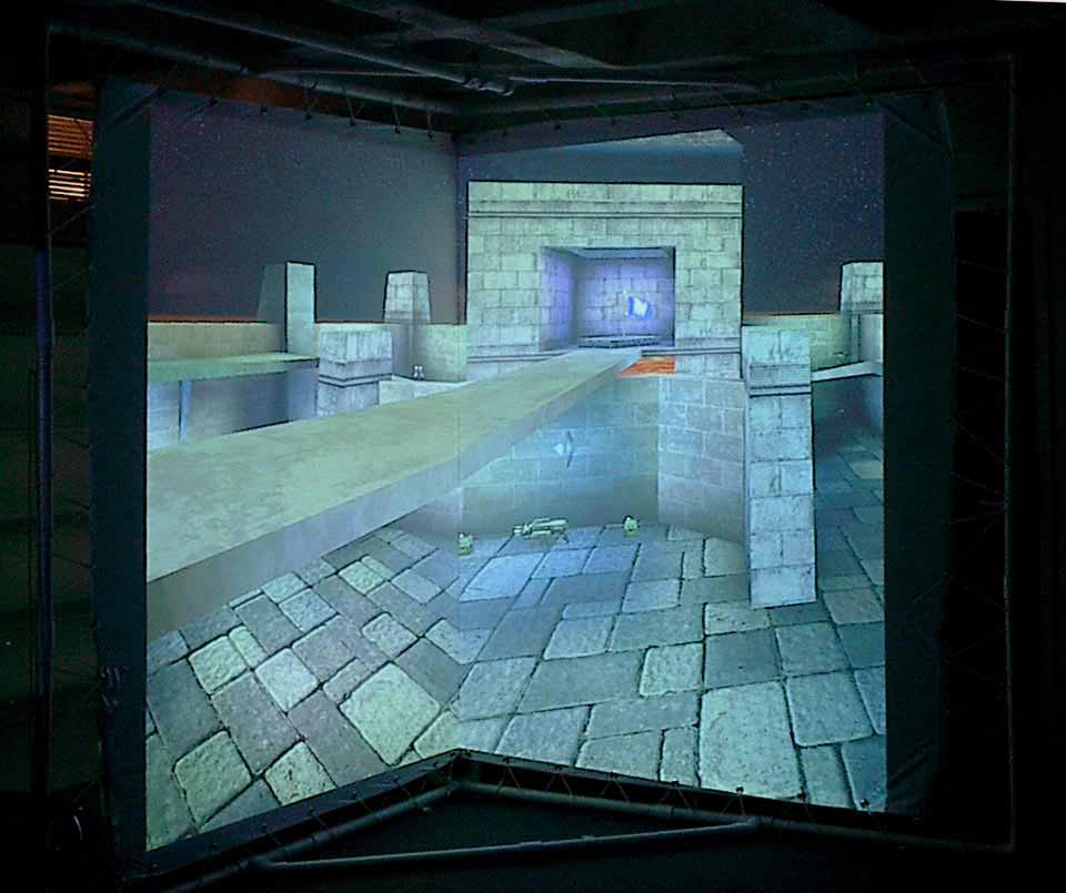
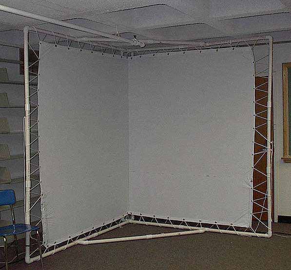
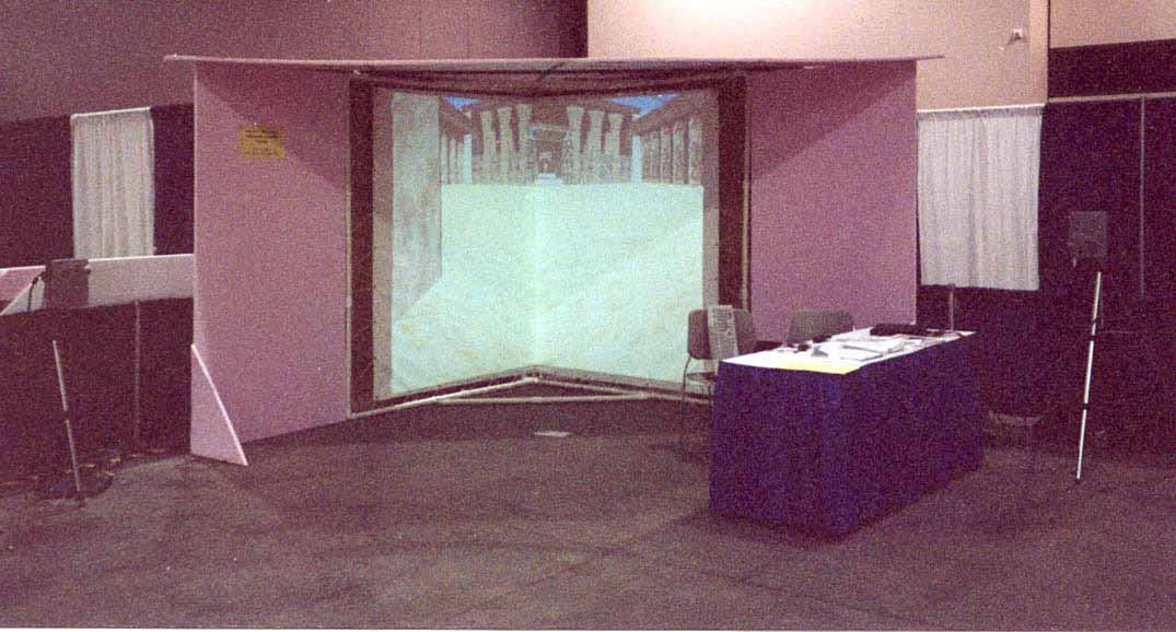
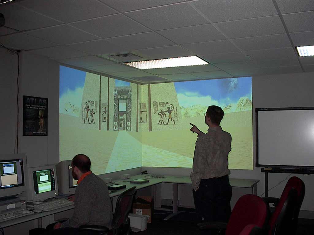
In this setup, two digital projectors are each mounted on a wall and pointed into the corner of a room, as shown in Figure One. Each projector displays on the wall perpendicular to its own. One edge of each projection lies along the corner itself, so the two images abut. If the projectors are bright enough and the wall is both clean and white, no screen material is needed. Otherwise, you can use some covering material like very large sheets of paper, white foam core, white plastic, or Tyvek®. Figure Two shows the layout, from overhead, of the components used for the corner CaveUT setup shown in Figure One. The setup is controlled from the server computer, labeled "PC Operator Console" on the diagram. From the Console, data is sent to the Net Hub, and from the hub to each secondary (client) PC. Each PC runs a client version of Unreal Tournament 2004 in client mode and sends its data, in turn, to the Projector associated with it. Each Projector displays its portion of the UT2004 player's view to the corresponding screen (or, in this case, portion of wall). The setup shown in Figure One has its ideal viewing point, or "sweet spot," at the location shown in Figure Two. This gives a viewer there approximately 100 degrees of horizontal FOV. |
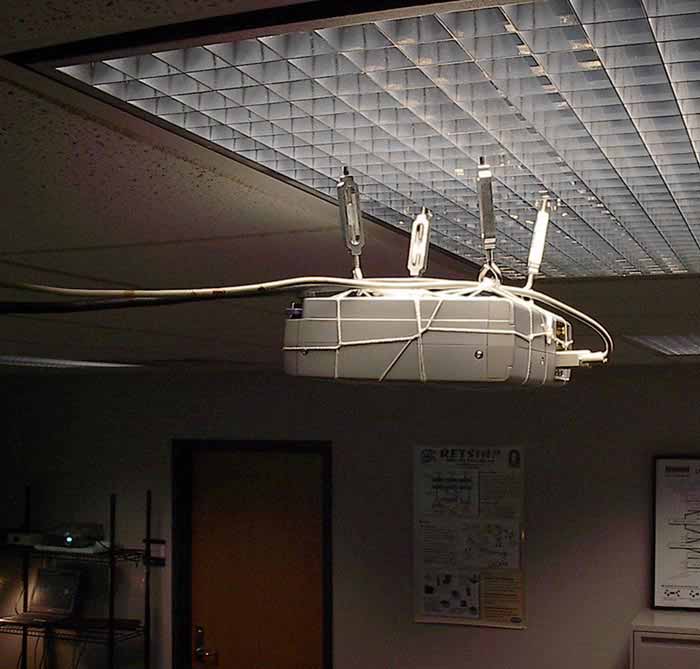
Note that the setup shown in Figure One differs from the diagram slightly: Its the projectors are not turned sideways. One is on top of a bookshelf and the other hangs upside-down from hooks in the ceiling, as shown to right, demonstrations of the ways one can (and often must) improvise when accommodating a CaveUT setup to its environment. |
Following is an inventory of the parts used for the two-walled V-Cave (which was described on the Examples of CaveUT Implementations page, excluding the projection surface. In many cases, setting up an implementation of CaveUT can require even fewer materials, and should not require more.
Standard 100mbps Unmanaged Ethernet Hub ($50-$100)
It's fine to purchase an inexpensive hub (which is also sometimes called a "Network Switch"), but be sure to get one that is physically rugged, particularly if the CaveUT setup is to be regularly transported.
Four 25' 10-based-T LAN cables and One Coupler ($100)
These cables are also often labeled as "RJ45 CAT-5e Patch Cables" or something similar. These lengths are sufficient for a CaveUT setup like the one shown in Figures One and Two; a more ambitious setup, or one where the console and client PCs are set up well away from the screens, will call for longer cables.
Three Standard 25' Power Cords And Two Surge-Protected Power Strips ($60)
Be sure to plug everything into the surge protectors for the safety of the equipment. It's also important to be sure its the surge protectors are of a good, reliable brand. If the CaveUT setup is to be regularly transported, it's also helpful to have protectors that are physically light and small.
You could even choose to use an Uninterruptible Power Supply (a UPS) if you are uncertain about the quality or stability of your power supply.
Three Desktop Computers (Approximately $1500 to $2500) or,
Three Laptop Computers (Approximately $4000 to $7000)
Desktop computers are best-suited to a CaveUT implementation that is intended to stay in one specific location; laptops are better suited to implementations that will be moved on a regular basis (such as for computer and trade shows, for demonstrations at various schools and college departments, etc.).
Regardless of whether the machines are desktops or laptops, they
should be fairly robust, in terms of graphics cards and processor speeds, to produce the best graphics performance.
The V-Cave shown in Figure 1 utilized two Pentium 4 1.1GHz laptops, with substantial amounts of RAM and geForce2 cards, for the client machines; they were operated at 1024x768 resolution. The console laptop was much more modest, a Pentium 3 800MHz machine with 128Meg RAM, running Windows NT.
Typically, the console machine only has to be strong enough to provide smooth interaction.
The machines mentioned above are more than enough for showing off CAD models. If a CaveUT setup shows off lots of human figures, or very complex models, a falloff in performance may result. (Should this happen, and should no more robust hardware be immediately available, a useful trick is to reduce the Unreal Tournament 2004 resolution and rendering quality values.)
The client machines must be running Windows, at least until the Linux port is done. However, the server machine can run MAC-OS, Windows, or Linux, and it only has to be fast enough to provide smooth interaction between the machines in the network.
A Spare Keyboard and Two Keyboard Extension Cords ($35)
This extra keyboard is the input device used by the player to navigate and interact with the virtual world. A CaveUT setup can use any kind of control device -- keyboard, joystick, trackball, or other favorite game peripheral.
The extra extension cords are recommended for a setup in which the player is also the operator; it gives the player/operator much more freedom of movement, which is particularly useful during demonstrations and presentations.
|
Two Tripods ($200+) |
|
Two Digital Projectors (Approximately $7000)
Important Note: It is critical that small projectors, those weighing nine pounds or less, be purchasd for a CaveUT setup. Small projectors are:
Warning: just because a projector can be turned upside-down to be ceiling mounted does not mean it can be turned sideways; some are engineered so that air will flow them correctly when they are upside-down but not when they are sideways.
A Tangent on Keystone Correction: Most commercially available projectors have a lens inside them which introduces a keystone correction. This
causes the beam to spread upward as shown in the illustration to the right. In the illustration, the left-hand projector has its beam configured normally; the right-hand projector has its keystone correction implemented, giving it a lop-sided projection beam.
This feature of projectors allows a projector to be set up on a conference room table and have its display shown on the wall without the projector having to be propped up on books or other elevators.
This feature is a very good thing. It allows for the arrangement shown in Figure Two. With the projectors turned sideways and keystone correction implemented, the projection beams allow the viewer to stand about as close as most people ever want to. In general, this it feature provides a CaveUT implementation with two possible locations for a projector to project onto a particular screen.In the boardroom example, an upside-down projector, mounted on the ceiling, could project onto the same screen as it would if it were just sitting on the main table. Said another way, the keystone correction for a sideways mounted projector can be made to go left or right simply by rotating the projector 180-degrees. In fact, the two projectors in the V-Cave are turned sideways in opposite directions.
Without this advantage, the BNAVE could never have been made as large as it is, given its space constraints.
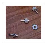
Materials for Mounting Plates for The Two Projectors (Cost Negligible)
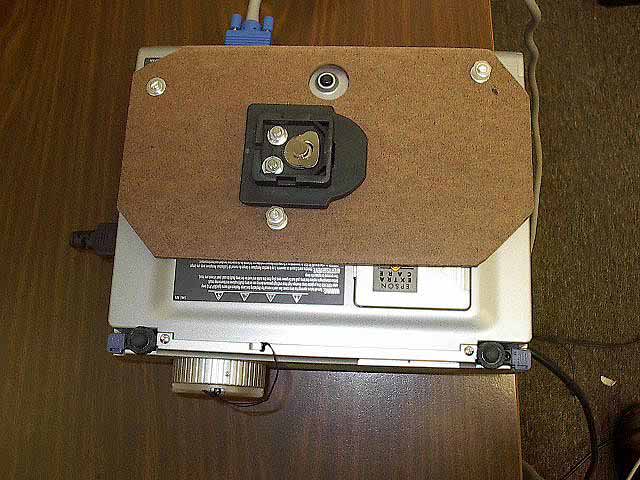
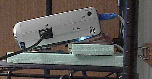
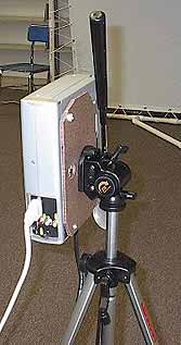
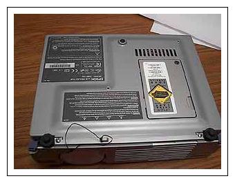
The projectors need to be attached to the tripods. Most projectors are designed with some means to mount them upside-down from a ceiling; most have threaded bolt-holes cut directly into the projector case. This is a flimsy arrangement, particularly since the projector cases are often made of plastic. It's much better to spend a little time making mounting plates that attach directly to the projector case, then attach the tripods to those mounting plates.
The figure to the right shows a projector with its mounting plate attached.
(It's also true that for most projectors, mounting brackets are available for sale. However, they are usually designed for ceiling mounts, they are always outlandishly expensive for what they offer, and they are sometimes not engineered to allow the projector to be mounted on a tripod. For all these reasons, it's better to build mounting plates from scratch.
An easy approach is, for each projector, to use one-foot square pieces of 1/4" hardboard, metric screws that correspond to the threading of the holes in the projector cases, and some other very small items. (Detailed instructions for building mounting plates from scratch appear below, under the headline Building Projector Mounts.) It's best not to purchase the mounting plate components in advance -- wait until the projectors themselves have been purchased and the setup of the entire CaveUT implementation has been determined, at which point your precise needs will be readily evident.
Materials For Screens (Cost Variable, $0-$650)
Finally, there are the screens themselves -- the surfaces the CaveUT images will be displayed upon.
The cost of screens varies widely. The cheapest screens consist of two walls that are already painted white -- net cost zero. Other approaches to screens include purchasing large commercial projection screens or fabricating screens from scratch, designed to the specifications appropriate to your own CaveUT setup.
Important: With bright projectors, especially, you can get away with all sorts of substandard projection surfaces, but there absolutely cannot be any gaps or ridges in the material. Also, any join between two screens has to be absolutely perfect. Much of design of the V-Cave is centered on keeping the seam between the two screens clean and straight.
Below, under the headline Building Portable Screens, are instructions for building an inexpensive set of screens suited to a portable CaveUT setup.
Screen Material ($20-$500)
The screens shown above were constructed with two 70"x88" sheets of material used in the making of banners -- the sort that proclaim the opening of new restaurants or the availability of apartments for lease. The precise material used in these screens was "FS 12oz White H/G" with grommets at one-foot intervals on all sides. Such material can be purchased from many banner printing companies. In the V-Cave setup, the sheets cost a total of $160.
For the first V-Cave prototype, white shower curtains, with grommets added to the edges by hand, were used. This worked reasonably well, but the banner material is much better. Composed of three layers of plastic -- one black layer in the middle and two white layers on the outside -- banner material prevents light from getting
though, which can be important in an environment with a lot of ambient light. In a front-projection setup, any backlight will degrade the projected image.
It's also possible to order professional screen material from companies that sell projection and presentation supplies and components. (Cost for enough material for two screens would be approximately $500.) These materials fold up nicely and does not crease like banner material does. You can usually ordered with grommets installed and some screens are suitable for back-projection.
It's helpful to remember that the better the projection surface is, the more of the projector's light it will reflect. However, if you have a dark room and good projectors, you can get away with using inferior screen materials.
As a rough guess, banner material reflects about 80% as much light as a professional screen, while shower curtains reflect about 60%. The 1000-lumen bulbs used in many projectors look like 800-lumen bulbs when shining on banner material or 600-lumen bulbs when shining on shower curtains. In ideal circumstances -- that is, in a dark room -- shower curtains can be more than sufficient.
Note also that shower curtains do let enough light through (about 40%) to be
used as a rear-projection material, again assuming a sufficiently dark
room and sufficiently bright projectors.
Another advantage to very bright projectors is that they wash out
imperfections on the screen. Dirt, scratches and creases usually get washed out in the brighter image.
Finally, any projection surface, except a professional screen material, can change the overall color of the scene projected onto it. It's possible to compensate for this by changing the color balance in the projectors.
Plastic Hammer ($20)
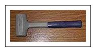
The screen frame will be made of PVC pipes. This plastic hammer is for pounding it together and apart.
Avoid the black hard-rubber mallets. They smell bad, leave black marks on the pipes, and tend to become damaged by use.
|
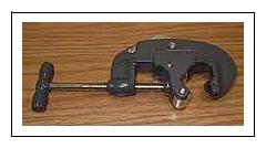
Pipe Cutter ($25) |
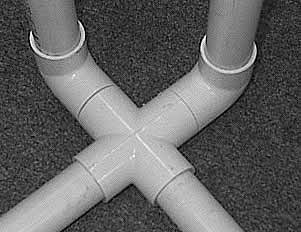
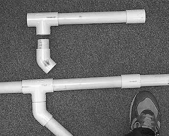
Screen Frame (90' of 1 1/4" PVC Pipe) ($50)
Obviously, there all sorts of materials are suitable for the construction of a screen frame. PVC pipe is a good choice because it's cheap, not-too-heavy, easy to work with, easily replaced, and rugged.
Cut the pipe into the following pieces:
| 27 | 31" segments (one is a spare to account for loss or breakage) | |
| 2 | 27.5" segments | |
| 4 | 12" segments | |
| 8 | 2.5" (tiny) segments |
You will also need the following specialized PVC pipe pieces, normally available at the same retailer that supplied the PVC pipe:
| 19 | straight joiners (one is a spare) | |
| 9 | 90-degree turn joiners (one is a spare) | |
| 3 | four-way "cross" joiners (one is a spare) | |
| 5 | 45-degree turn joiners (one is a spare) | |
| 5 | T-joiners (one is a spare) |
When these components are first assembled into a frame, it will be terribly unstable, wobbling drunkenly at the merest push. However, once the screen material is on and stretched, the whole thing will become much more stable.
|
|
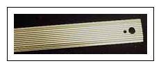
16' of Carpet Seam Binder ($10) |
Package of Fine-Grit Sandpaper ($3)
Sandpaper is used for grinding off the sharp corners of the carpet seam binders.
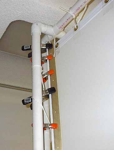
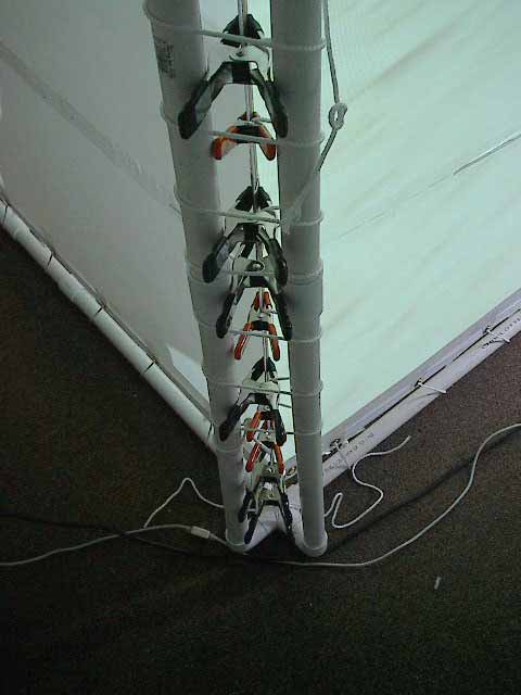
Twenty 2" hand clamps ($40)
See the left-hand illustration beside the 16' of Carpet Seam Binder headline. The black clamps shown there are 2" clamps. In the example shown in the illustration, ten 2" clamps and ten 1" clamps were used, but it's easier to use 2" clamps exclusively, and these instructions assume that's the technique that will be used. (In other words, do as we say, not as we do.)
As the illustration shows, these clamps attach the carpet
seam binders to the screens, effectively creating a strong seam. The clamps also act as grommets in that nylon cord will be threaded through them as shown in the illustration under Step 3 beneath the How to Assemble the Portable Screens headline below. During assembly, you'll thread the nylon cord through the clamps as shown in that illustration.
|
The general configuration of this portable setup is shown on the illustration of the screens (without projections) under the Portable V-Cave headline on the Examples of CaveUT Implementations page. |
Step 1
On a clean floor or a large clean surface, lay one of the screens face-up.
Step 2
Lay the other screen on top of it, face-down. The grommets on the two screen pieces will not line up, but that's not important.
Step 3
The "stack" of two screens is rectangular. Choose one of the long sides of this stack and lay three of the carpet seam binders on top of the screens, parallel to that edge and about 1" to 1 1/4" from the edge.
Arrange the other three carpet seam binders in exactly the same way, but upside down, underneath the screens, along the same edge. The two rows of seam binders should be facing each other.
One by one, put the metal clamps into place, so the seam looks like the one shown in the illustration to the right. While doing this, make sure that the edge of the two screens is pulled taught. At this point in the process, there will be creases and wrinkles in the screen material, and it's important that no creases or wrinkles remain between
the seam binders.
In addition, it's important to make sure that the carpet seam binders are exactly the same distance from the outer edge of the screen at all points. In other words, they need to always be exactly 1" from the edge all along the length of the seam, or all exactly 1 1/4" or even 1 1/2", so long as they are consistent.
Be careful that the bottom pieces perfectly line up with the ones on top.
Assembly of this step is easiest when three people work together, though one person can do it.
Finally, it's best not to stress too much about this step. If it is done incorrectly, it's possible to fix matters later.
Step 4 |
Step 5
Carefully, move the screens to the frame. One person can do it, but it's easier with two people involved.
Bring the top end up to the top corner of the frame.
Tie the piece of cord around the 4-way cross piece joiner at the top of the frame. Be sure to wrap the cord through opposite corners of the cross piece, as shown in the illustration that accompanies Step 4. This will allow the seam to hang directly underneath the center of the cross piece.
Step 6
Tie the bottom of the seam to the bottom cross piece in exactly the same way. Make it tight, but not too tight, or the clamps may start to slip off the carpet seam binders.
Step 7 |
|
Step 8 |
Step 9
Thread the other screen, at the top, in exactly the same way.
Step 10
Thread the bottoms of the both screens in exactly the same way you did the top edges. The loose ends of the ropes for top and bottom should meet in about the middle of the outer edges.
Step 11
Thread one long piece of cord through the hand clamps behind the cental corner of the frame, as shown in the illustration beside Step 3. Start at the top and work your way to the bottom. Don't pull the cord too tight at this point, but don't let it hang in loops. Attach it at the top and bottom by wrapping it around one spur of each crosspiece a few times, but don't tie it off.
Step 12
Gently, but firmly, tension the top or bottom edge of one screen, whichever one has the most room between the edge of the screen and the frame. Start at the first loop of the rope, which goes though the first grommet nearest to the frame's central corner. Pull the slack out of that loop and get rid of the slack by pulling on the next loop. Then pull the following loop and so on. Keep going past the outer corner of the screen and go down (or up) along the outer edge of screen. Eventually, you will reach the end of cord. All
the slack will now become more rope hanging off the end.
Secure it by tying a slip-knot or just wrapping it around the PVC pipe a few times.
Step 13
Tension the other side of the screen, the top or bottom, and work out to the outer edge, just as described in Step 12.
Step 14
Tension the other screen in exactly the same way.
Step 15
At this point, take a serious look at the inner corner of the screens. It should bow inward a bit, toward the viewer. This is not a problem; the bowing will be corrected in the next stop.
Take note of whether the screen is clean and consistent, and whether there are any puckers or wrinkles caught in it. If it is flawed in these ways, then you can fix it: Take all the clamps and the carpet seam binders off of the back of the seam, but let the carpet seam binders stay tied to the screen frame. Remove the cord that you had strung
through the clamps. Now, rebuild the seam in much the way you did it in Step 4, starting from the top and work down. You will find that the process is easier this time, and you should get a good, straight edge.
Step 16
Move along the edges of the screens, tightening the loops of rope as much as necessary to make the screen hang flat and to make the main corner clean and straight. You will find that you have to pull a bit more near the center of each side of each screen. This phenomenon will be familiar to anyone who stretched a canvas over the traditional
wooden frame to make a painting. The PVC pipes in the frame will bow in a bit, which is normal and not problematic.
Done
Now the screens are finished.
Obviously, portable screens are useful for CaveUT implementations meant to be moved from site to site, chiefly for purposes of demonstrations. It's not usually practical to carry oversized sunshades to shield the screens from bright lights, but it's similarly unrealistic to expect all venues to have the best ambient light for a CaveUT's purposes... and bright lights wash out the images projected on the CaveUT screens.
One such instance was CHI 2002, where the VCAVE was demonstrated. There, it was necessary to improvise a temporary overstructure to shade the screens from the bright lights in the convention hall.
About $100 at a large hardware/construction supplies store purchased enough 4'x8'x1" sheets of pink rigid foam insulation (in this case, Foamular® by Owens Corning). This sort of material is ideal for light improvised construction of this sort -- it's light, strong, cheap, stable, can be cut with a steak knife, and can be attached with packing tape and standard wood glue. (On the down side, it's also extremely flammable, making it unsuitable for permanent displays unless you treat it further with some sort of fire retardant.)
The roof of the structure constructed to shield the VCAVE from overhead lights was a right triangle (11.31' x 11.31' x 16') made from three sheets of Foamular® -- as shown here, the two corner pieces are both taken from one sheet. The edges were glued together and additionally taped with clear packing tape.
Once the pieces were taped together, they became remarkably stable. It was then possible to maneuver and cut them as if they were a single piece. (A tip to such construction: Packing tape will usually peel off with time, but not until it has given glue time to dry. For fast, improvised construction of this sort, it's convenient to glue the pieces together for their long-term stability, then immediately tape them for short-term stability.
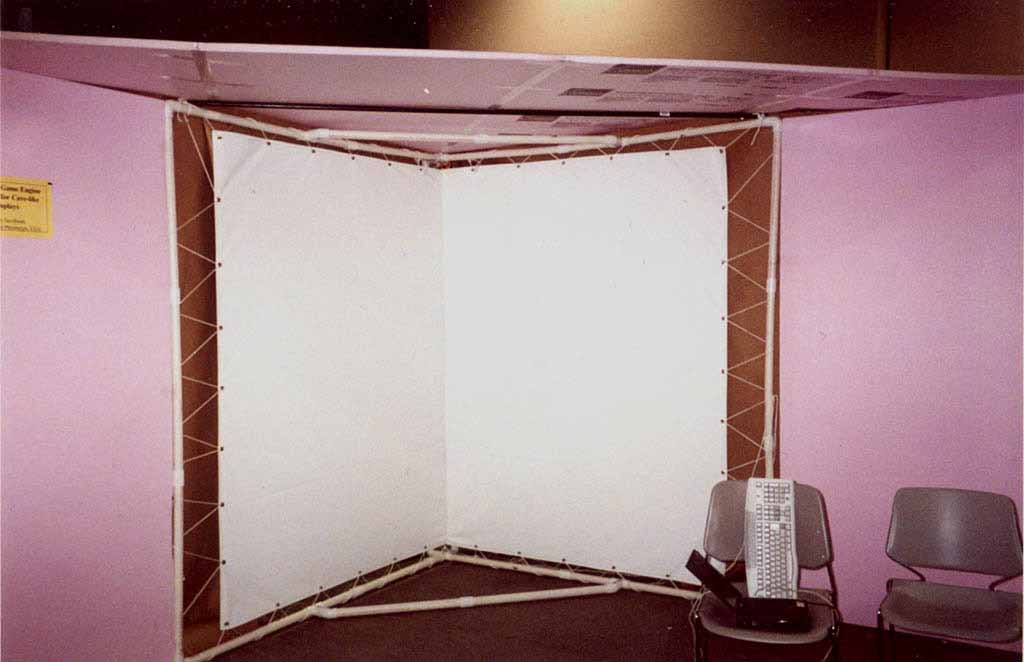
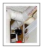
As shown to the right, simple brown construction paper served to block light from coming through the lacings between the frame and the screens. (In this case, it was not necessary to use it behind the screens, as this particular screen material was already opaque.) In a similar situation, if your screen material is at all transparent and you are using front-projection, you must put something behind the screens to prevent light from leaking through the screens and washing out the projection image. Finally, there is single black bar supporting the frame's roof, which which is barely visible in the illustration to the right. This as just a water-pipe laid on top of the PVC pipe structure and tied onto the frame with two bits of rope. The whole thing went into the trash once CHI 2002 was done. |
Earlier, we discussed the fact that most CaveUT implementations will require that mounting plates be fabricated for the projectors. Here are some guidelines for fabricating them.
First, some warnings:
Step A
Make a plate of some flat material and cut it to match the dimensions of the side of the projector with the bolt holes. Hardboard and Plexiglas® are ideal, but any construction material that is sturdy, lightwait, and suitable for cutting will do.
If the plate covers up a vent on the projector, then cut an equal-sized hole in the plate to let the air through.
Step B
Drill a hole in the plate for each bolt-hole. Be sure to carefully measure the bolt-holes' relative locations and mark where you want to drill into the mounting plate. Guessing, rather than accurately measuring, is counterproductive.
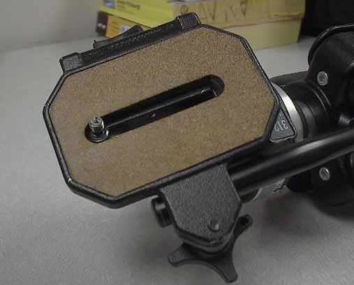
Step C
Add hardware to the mounting plate which will allow it to attach to the tripod with a bolt that fits through the appropriate slot in the tripod's head. Any number of nuts or nut-and-washer combinations available at the hardware store should serve admirably.
Probably the most durable and effective approach, assuming ready availability of the appropriate tools, is to make the mounting plate out metal and weld a steel nut to the middle of it. Then it's a trivial matter to attach the plate to the tripod's face-plate with a steel bolt. Steel is best, as the entire weight of the projector will be resting on just the threads in the nut and the tip of the bolt.
It's also not a bad idea to put some space between the mounting plate and the projector by using longer screws and placing additional washers or nuts between the projector and the mounting plate. This allows permits use of a larger, sturdier nut for the point where the tripod bolt attaches to the mounting plate, and provides even more room for air-flow and cooling of the projector.
|
Step D |
|
|
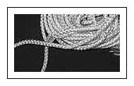 100 feet of 1/4" nylon cord ($3)