V: Configure View Rotations and Offsets
Below are the contents of the default CaveUT.ini file:
[CaveUT.Spectator]
CaveRoll=0.000000
CavePitch=0.000000
CaveYaw=0.000000
CaveOffsetX=0.000000
CaveOffsetY=0.000000
CaveOffsetZ=0.000000
CaveFOV=100.000000
OffAxis=No
FOVleft=-45
FOVright=45
FOVtop=36.87
FOVbottom=-36.87
[CaveUT.CaveUTInteraction]
RotateIncrement=0.250000
OffsetIncrement=0.500000
FOVIncrement=0.500000
For the moment, we are only concerned with four parameters: CaveRoll, CavePitch, CaveYaw and CaveFOV. (They are shown here in bold face -- they are not bolded in the actual cave.ini file.) Follow these steps:
Step 1: Place the Screens
Decide where you want to place the screens of your immersive display. You can have up to 31 screens, with each one arraigned in any orientation to the viewer.
Before physically setting up the screens, first make a diagram! Draw it out carefully, with all the important angles and sight-lines specified. You will have to use a fair bit of trigonometry as you go. If you are new to it, or need a review, this tutorial is among the best available online.
The term "screen", as it is used in this document, refers to the portion of the physical display that is actually showing pixels generated by the PC's video card. Almost always, there is some extra projection screen or monitor material around the edges of computer driven display.
For an immersive display, it is usually best to have as much horizontal display area as possible and to balance the left and right halves of it. That way, the viewer sees as much (horzontal view) in the left eye as in the right eye.
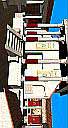
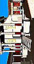
However, humans have more vertical range down than they do up. So when you arrange your screens, it's usually best to sacrifice some display area at the top for more display on the bottom. The image on the left illustrates this for one screen.
Extending this idea, it's generally better to have a floor screen than a ceiling screen.
Step 2: Find the Default Sweet Spot
While multiscreen immersive displays can be irregularly shaped, the vast majority have symmetrical designs, because they are easier to build and easier to work with. CaveUT naturally supports symmetric and asymmetric (irregular) displays equally well.
Symmetrical displays have a useful property: There is a single symmetric view frustum such that when all the screens use it, all the screens' frustums will meet at a common point -- the default sweet spot.
Three examples are shown on the right: the BNAVE (ignoring its floor), MiniCave, and V-Cave. The side view illustrates that the viewer's eye is level with the midpoint of each screen for each display.
The default sweet spot is the easiest one to configure and is adequate for many immersive displays, such as the MiniCave. You can calculate it while working with just the view rotations and the CaveFOV parameters in cave.ini.
If the sweet spot needs to be elsewhere, it's still best to get everything working first for the default sweet spot.
The procedure for finding the sweet spot is quite simple:
- Graph or sketch where the screens are or will be.
- Draw a perpendicular line from the center of each screen.
- If the display is symmetrical, all of the perpendiculars will intersect at a single point, which is the default sweet spot.
The diagram on the left shows where the sweet spot can be found for the BNAVE in an overhead view. Since all the screens are the same height, the vertical location of the sweet spot must be half the length of a screen up from the surface the BNAVE is resting on.
For more complex displays, it is best to use a 3D modeling program to "draw" your display in three dimensions before using this procedure.
|
Step 3: Decide Where to Put the "Control Point"
Even a single screen display has a sweet spot, and in a normal UT2004 game it is always located directly in front of the center of the screen, as shown on the left.
As we'll explain in Step V, below, the distance from the screen is determined by the field-of-view (FOV) parameter. Notice that the viewer's the line of sight goes directly from the sweet spot to the exact center of the screen. It determines the direction of pure forward motion and the direction the player's weapon weapon fires when the player shoots it.
From now on, we will call the point on the screen where the line of sight intersects the screen the Control Point.
By extension, a multiscreen CaveUT display also has a control point, usually located on the center screen, as with the BNAVE and the MiniCave, depicted in the image on the right above.
For your display, you need to decide where you want the Control Point to be. At this stage, when you are using the default sweet spot, the view frustums have to be symmetrical, therefore, the control point has to be in the center of one of the screens. So this exercise is really about choosing one of the screens, presumably the center screen.
While all symmetrical displays have a default sweet spot, some asymmetrical displays do also. The BNAVE, with its floor screen active, is an example. As long as you can draw a perpendicular from the exact center of each screen a common point of intersection, then the multi-screen display has a default sweet spot.
Step 4: Make Note of the "Line of Sight"
The "line of sight" starts at the sweet spot, goes through the control point, and continues onward into the virtual space. In that sense it is like the view frustum. Discussions later on this page require calculations based on the line of sight.
Step 5: Determine the Field of View (FOV)
For each screen, you need to figure out what its horizontal FOV angle should be, so the apex of its view frustum will be located at the sweet spot. The best way to do this is go back to the drawings you used to determine the default sweet spot. Then draw a line from the sweet spot to the edge of each screen. For each screen, calculate the angle between the two lines going from the sweet spot to its two edges, with trigonometry. All you need is the width of the screen (assuming an overhead view) and the distance from the sweet spot to the screen.
While CaveUT does all sorts of things to the computer's display, the engine for the UT2004 game on each computer has no idea all this is going on. It still thinks that it is generating a view to be shown on an ordinary monitor sitting on someone's desk. For this discussion, let's call the width of a normal unmodified UT2004 display the "long axis" (because the vast majority of computer displays are wider than they are tall), with the height of the screen the "short axis."
Now, one more term: the "aspect ratio" of a display is just the ratio of its height and its width, by convention ( width / height ). In our new terms, that would be the ( long-axis / short-axis ). Most commercial displays have a 4/3 aspect ratio (for example, 800x600 or 1024x768).
We will need these new terms because determining the right FOV gets a bit more complicated when the screens are sideways, as they are in the MiniCave, the V-Cave and the BNAVE (except the floor.) The CaveFOV parameter in cave.ini allows you to set the game's generic FOV setting. This allows you to set the FOV of the long-axis, at which point the game will calculate the FOV of the short axis to be just right so the display's aspect ratio stays the same.
For example, setting the long-axis FOV to 90 degrees will automatically set the short-axis to 53.13 degrees.
This formula shows the relationship between the long-axis and short-axis FOVs:
tan( L ) = A * tan( S ) Where:
L = ( Long Axis FOV ) / 2
S = ( Short Axis FOV ) / 2
A = ( Long Axis Length ) / ( Short Axis Length )
From this, you can calculate the short-axis FOV from the long-axis FOV and vice-versa:
S = atan( 1/A * tan(L) ) L = atan( A * tan( S ) )
For example, the diagram on the right depicts an overhead view of the MiniCave. Because the screens are turned sideways, the 60-degree FOVs in the drawing are short-axis FOVs. So what does the long-axis FOV have to be so we can get a 60 degree short-axis FOV?
S = ( Short Axis FOV ) / 2 = 60/2 = 30 degrees
A = ( Long Axis Length ) / ( Short Axis Length ) = 1024/768 = 4/3
L = atan( A * tan( S ) ) = atan( (4/3) * tan(30) ) = 37.59 degrees
( Long Axis FOV ) = 2 * L = 2 * 37.59 = 75.18 degrees.
Set the CaveFOV parameter in cave.ini to 75.18 degrees to get a short-axis-FOV of 60 degrees.
Step 6: For Each Screen, Determine the Roll, Pitch and Yaw
If you have a screen directly in front of the user, as with the BNAVE and the mini-cave, keep its Roll, Pitch and Yaw values zero. The screen is already where it needs to be. Each change of the other screens' views will be created by starting with the (virtual) front view and rotating it until it matches the its intended physical screen.
For example, in the BNAVE, the image on the right screen view would start out being the same as on the front screen. The user would rotate the view frustum around the default sweet spot by +80.5 degrees, as shown in the diagram on the right. A negative value, like -80.5, turns the view to the left. You are actually rotating the virtual line of sight until it intersects with the center of the side screen.
Set the Pitch (up-down) in the same way as the Yaw. For example, the floor screen image in the BNAVE is produced by setting the pitch to -90 degrees. Alternatively, setting it to +270 would have the same effect.
Set the Roll. This will rotate the entire scene, on the flat screen, around the control point. This is especially handy when you want an individual screen to be taller than it is wide. All of the vertical screens in the BNAVE, the mini-cave, and the V-Cave are this way. Positive numbers rotate the scene clockwise, negative numbers rotate it counter-clockwise.
For example,
CaveRoll=90.0
will turn the scene sideways, as shown on the right. Or, you can rotate the image counter-clockwise with:
CaveRoll=-90.0
which will also turn the scene sideways, but in the way shown on the left.
Step 6: For Each Screen, Set the cave.ini Values
Open cave.ini in a text editor and change the values for the CaveRoll, CavePitch, CaveYaw, and CaveFOV parameters to the values you determined. All angles are measured in decimal degrees.
When you are doing this for the first time, it's worthwhile to play around with these values, just to get a feel for what the changes look like. You will be amazed at how much difference a single degree can make. Save the file and the changes will be visible the next time you use that client to connect to the server.
Final note: be sure to use a text editor that will write the cave.ini file in text-only form. Notepad is good for this.
Step 7: Fine Tune the View Rotations
At this point, you should have a single contiguous view of the virtual space. If you eye is not at the sweet spot, things on-screen will look bent where the screens meet, but that's normal. The main thing to look for at this point is how well the images line up where the screens meet. They will probably be off a bit because of small, unavoidable irregularities in the physical setup.
You can fine-tune the Roll-Pitch-Yaw values on any individual screen from the keyboard for that machine. To do this, start CaveUT/UT2004 on your server and client machines, and be sure to click the clients' fire buttons. The help menu will only appear on a client machine when movement on its display is locked to the server's controls. In other words, you have to have CaveUT fully engaged and working, otherwise the debug menu simply won't appear.
Debug keyboard commands are:
| Shift+h | | Show debug menu |
| Ctrl+h | | Hide debug menu |
| |
| Shift+a | | Add increment offset X |
| Ctrl+a | | Subtract increment offset X |
| Shift+s | | Add increment offset Y |
| Ctrl+s | | Subtract increment offset Y |
| Shift+d | | Add increment offset Z |
| Ctrl+d | | Subtract increment offset Z |
| |
| Shift+z | | Add increment rotation pitch |
| Ctrl+z | | Subtract increment rotation pitch |
| Shift+x | | Add increment rotation roll |
| Ctrl+z | | Subtract increment rotation roll |
| Shift+c | | Add increment offset yawchanged |
| Ctrl+c | | Subtract increment offset yaw |
The first two commands just toggle the debug menu on and off. The third set allow you to add or subtract a numeric value called "increment" to/from Roll Pitch or Yaw with a single keystroke. Press the key more times to get a bigger change. Play around with these to get a feel for what the changes look like.
The second block of commands allows you to add a permanent offset to the client's viewpoint with respect to the player's view on the server.
The X, Y and Z refer to the coordinate axies of the game. The X axis governs left-to-right movement. The Y axis governs up-and-down movement. The Z axis is depth, or forward-back.
Try to avoid using the offset adjustments, because they can be problematic. First, if you have even a small offset, it is possible to put the view though a wall just by pressing the server-player up against that wall. Second, the apparent shift in the display will be greater for objects up close than for far-away objects, which can be terribly confusing and ineffective.
Strictly speaking, you don't need the offsets. It's always possible to get the screens to line up with each other just by using the rotations and the zoom feature on the projectors. Still, there are times when the offsets are too handy to ignore.
The values of "increment" are stored in the last part of caveut.ini:
[CaveUT.CaveUTInteraction]
RotateIncrement=0.500000
OffsetIncrement=1.000000changed
As you might guess, you can adjust the size of the change simply by editing these values and saving cave.ini. You will be amazed at how much difference a single degree can make, especially with Roll.
The changes made with the keyboard will be saved automatically when you exit UT2004. The numeric value of each keyboard parameter will be added to the corresponding parameter in cave.ini. Alternatively, you can change the cave.ini parameters manually, but you have to stop and restart the client each time, which is an inefficient use of effort.
Note: When CaveUT saves the offset values, it also writes a lot of other irrelevant material to the cave.ini file. This material is harmless and you can delete it if desired. Just be sure not to eliminate any of the CaveUT parameters.
So now you need to fine-tune the rotations and other parameters to make all the screens line up. It is usually best to tweak the center screen's configuration until it looks the way you want it to (which sometimes call for no changes at all), then line up all adjacent physical screens next to it, then fine-tune the rest.
Step 8: (Optional) If You Are Happy With the Default Sweet Spot, Then You Are Done
Otherwise, follow instructions in the next section.
Tip
Every time you edit CaveUT.ini, open it in your text editor, then close it when you are done. Many text editors will not allow another program to change the file while it is open for edit, so CaveUT will not be able to save your fine-tuning adjustments if the file is open in another program. Some text editors allow this (i.e. Notepad) but that can be confusing.
Last updated January 16, 2004.
URL: http://www.planetjeff.net/ut/CUT4Install5.html
This page is copyright © 2004 by Jeffrey Jacobson.
See this web site's copyright notice for information
on duplicating or distributing this page or its contents.
|
|